
You can use this website to stimulate the design of our plate heat exchanger. Please make sure on the following design conditions before proceeding to the next data entry step.
Q1 = Density x Heat capacity x ( 1 - 2 ) x 3 / 3600 [kW]
Q2 = Density x Heat capacity x ( 5 - 4 ) x 6 / 3600 [kW]
(For water, density is 1000, and heat capacity is 4.186kJ/kg deg.C.)
The heat duty on hot side (Q1) is equal to the heat duty on cold side (Q2); Q1 and Q2 must be the same (Q1 = Q2).
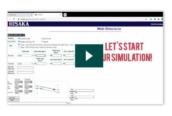
Plate Heat Exchanger Calculation method or some call it sizing of a plate heat exchanger can be simplified to two formula and by using constant figures for certain fluid combinations.
Q: Heat load, kW
ṁ : Flow rate, kg/h
Cp : Specific heat, kJ/kg℃
T : Inlet/outlet temperature, ℃
ṁ = W (m3/h) x ρ (kg/m3)
W : Volumetric flow rate
ρ : Density
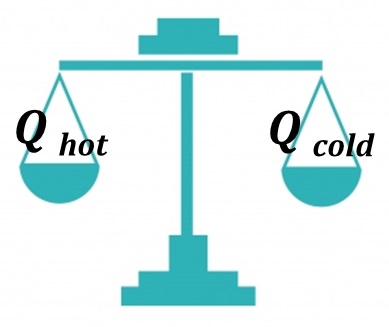
This calculation is done at first to determine how much Heat Load we are considering for heat transfer within this equipment. Your purpose maybe cooling, or heating, or even both at the same time. The heat load of cooling means the amount of heat load removed from the cold fluid during heat transfer in the equipment. Likewise, heat load heating means how much heat receive on the cooling fluid side. Based on this understanding, the amount heat removed from the hot stream is equal to the amount received for the cold stream.
T: Temperature, ℃
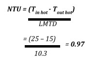
if Tin hot - Tout cold = Tout hot - Tin cold ,
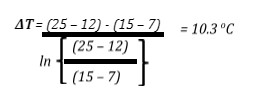
ΔT = Tin hot - Tout cold = Tout hot - Tin cold
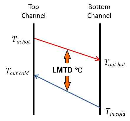
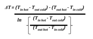
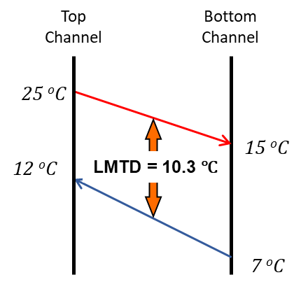
The logarithmic mean temperature difference (also known as log mean temperature difference, LMTD) is used to determine the temperature driving force for heat transfer in flow systems, most notably in heat exchangers. The LMTD is a logarithmic average of the temperature difference between the hot and cold feeds at each end of heat exchanger. For a given heat exchanger with constant area and heat transfer coefficient, the larger the LMTD, the more heat is transferred.
Q : Heat Load, kW (Amount of heat that will be transferred for the equipment)
U : Heat Transfer Coefficient W/m2K (Varies depend on combination of fluid, plate material, thickness, fouling factors as well as corrugation design that affect turbulence and heat transfer ability)
ΔT :LMTD, ℃ (value as per step ➁)
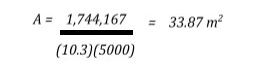
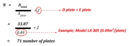
A : Heat transfer area, m2 (This value to be determined)
This formula purpose is for us to determine Surface area (A) of the plates required, considering values of the heat transfer.
| Water | 25 ℃ → 15 ℃ | 150 m3/h |
| Pure Water | 12 ℃ ← 7 ℃ | *** m3/h |
Q = ṁhot Cphot (Tin hot - Tout hot) = ṁcold Cpcold (Tout cold - Tin cold)
= [150 x 1000] x 4.186 (25 – 15) = [Wcold x 1000] x 4.186 (12 – 7)
= 1,744 kW ↔ Wcold = 300 m3/h
Q = A U ΔT = A x 5,000 x 10.3 = 1,744,167
| Application | Approx. U Value |
|---|---|
| Water - Water | 5,000 - 8,000 W/m2 . ℃ |
| Water - Brine | 2,000 - 3,000 W/m2 . ℃ |
| Steam - Water | 3,000 - 4,000 W/m2 . ℃ |
| Oil - Water | 300 - 800 W/m2 . ℃ |
If less than 1.5 = LOW (Select LX-Series)
While we can determine the minimum surface area required for the heat transfer. In actual operation, pressure drop is an important factor that affects flow rate. PHE with narrow gaps and corrugation will contribute to certain amount of pressure drop. The accumulated pressure drop across the flow line against the pump will result of the flow rate.
Prior to sizing any new PHE, sales engineer will confirm with user what is the allowable pressure drop. User will confirm on the pump ability against all the pressure drop include PHE’s contribution, and see the flow rate that can be achieved. If this step is not conducted properly, it will result in lower flowrate due to too much pressure drop in the line against the pump. Lower flowrate also will cause heat transfer not achievable. These are the common error when heat exchanger is sized smaller to cost down but cannot achieve performance.
In order to achieve reasonable pressure, drop, Plate heat exchanger has many different gaps, corrugation angles to meet customer needs. Sometimes, number of plates are added to increase plate channels to reduce pressure drop to the allowable. These are the important things to consider other than the calculation.
In recent years designs are more transparent and also users can do it by themselves using our web simulator. Accurate values are preloaded into the software that anyone can use it. Simulation can be done without tedious calculation of heat transfer coefficient and allowable pressure drop.
No 2, Jalan TP 2, Taman Perindustrian SIME UEP, 47600 Subang Jaya, Selangor Darul Ehsan, Malaysia.